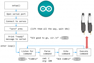
Programming the Arduino microprocessor to control the linear motors was based on (1) the parameters for cycling the actuators (and thus plunger array) up and down, and (2) the capabilities and limits of both the microcontroller and microprocessor. Specifically, the actuators needed to cycle between 2 positions — the start and final position, or the “compression off” and the “compression on” positions, which were separated by just a few millimeters. The linear motors each had an on-board feedback systems able to to detect position. Whereas the microcontroller cannot detect position, it can detect and control the length of time that current is being applied to the motors to cause actuation at a constant rate. Thus, multiplying the the rate constant by time, the microprocessor is able to detect position.
To control the location, and command the cyclical actuation, a for-loop was implemented. The for-loop is a conditional command that dictates “if condition X is met, then proceed to the next step, and if condition X is not met, repeat a function Y.” Thus, in such a system, function Y will be repeated until condition X is met. In this case, the for-loop controlled for position, and increased (or decreased) the length of the motor incrementally. If the position of the actuator arm was at position 0, and the ultimate goal was to get to position a position, “10” the actuators were commanded to actuate to position 1. This would then be compared to the desired position (10). Since position 1 is less then position 10, the actuators would then be commande to actuate another 1 unit, and so on, until position 10 was achieved. At this point, the system would reverse until position zero was achieved. This cycle would repeat 100 times, at which point the actuators would go to “neutral position,” in which they were raised to their maximum length, to allow for access by a fluid handling arm or other implementation.

