UPDATE: 3D Printing the Plungers

RECAP:

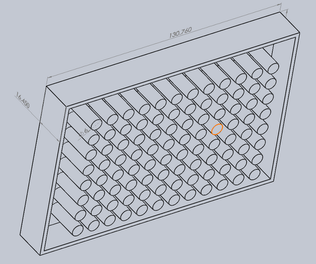
We chose to use 3D printing to manufacture the LidPlungers because the piece required precise and accurate dimensions to achieve uniform compression.

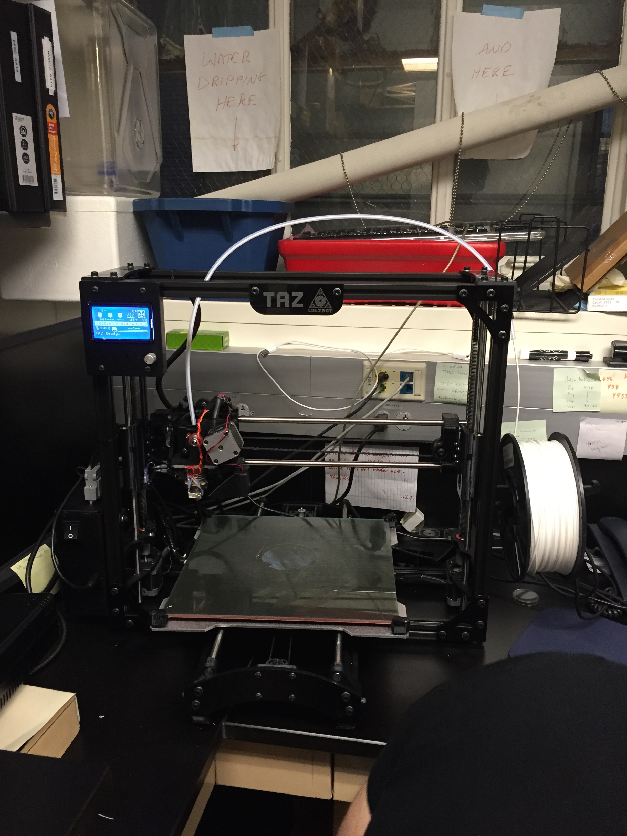
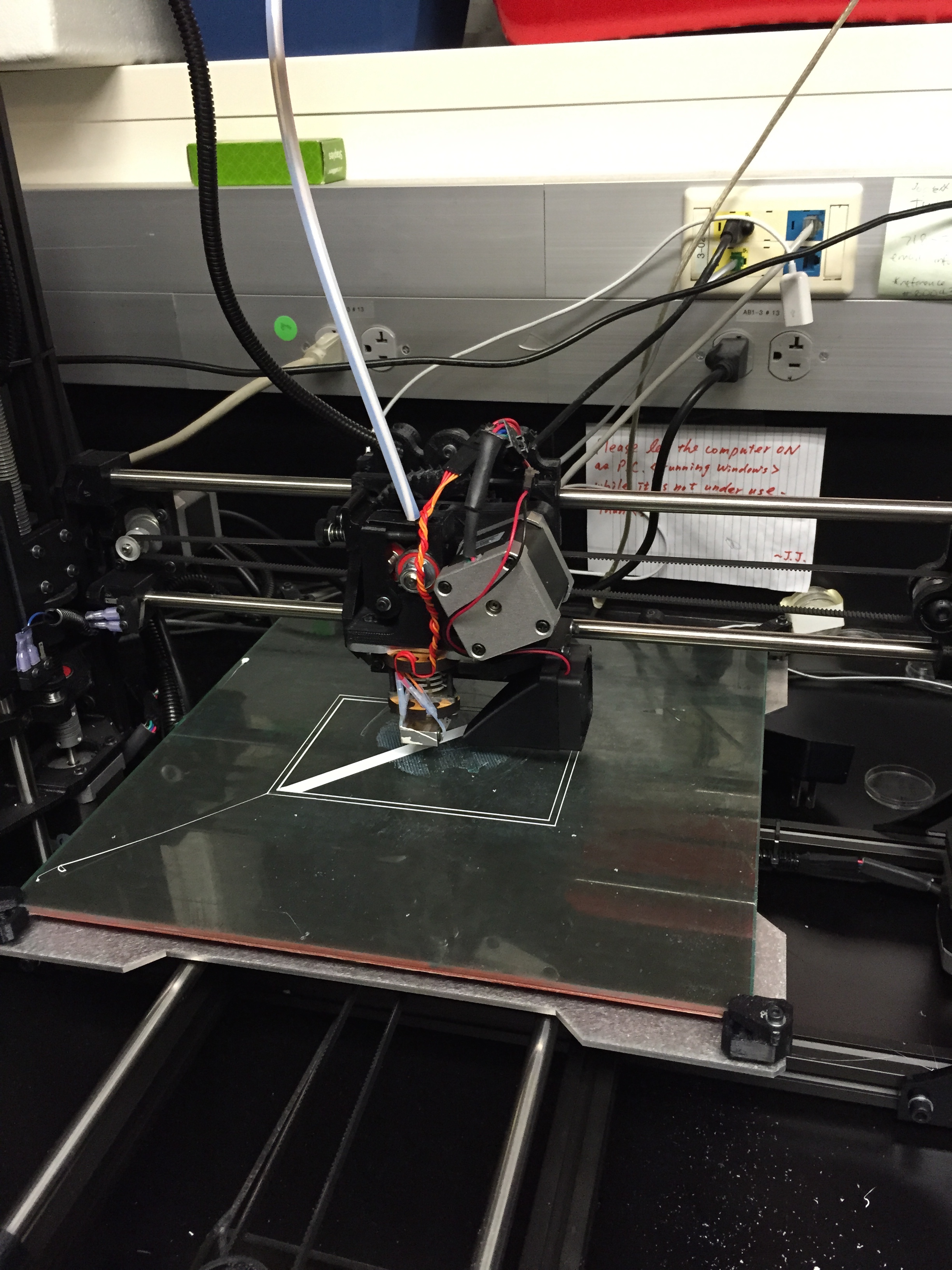
Our first attempts at printing used the Lulzbot TAZ4 with Kira (software) rendering software. The Lulzbot is a higher-end consumer 3D printer with ~75 micron resolution and can support multiple materials for printing.


UPDATE:

Our specific design turned out to be extremely challenging for the Lulzbot. On our first print attempts, the printer would lay the base structure before plastic built up at the release valve, causing the printer to fail. Conversations with the manufacturer revealed that the Lulzbot might not be able to handle repetitive, small designs (like the plungers) because it requires the plastic flow to start and stop so rapidly.

While a switch from Kira to Slice3 rendering software was able to get the printer to complete the piece, the final product was not structurally sound. Fragments of plastic were breaking off and the piece was extremely flexible.

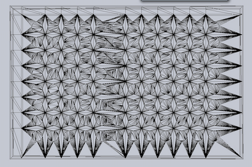
The team switched to printing on the 3D Systems Projet 3500 HD max, recently set up in the Mount Sinai Prototyping Center. A few features made this the more attractive printer; 1) it could print with much higher resolution, 2) its proprietary plastic would harden after printing, reducing breaking and bending, 3) it simultaneously printed a supporting wax to ensure no structural deformation.

The final product seemed extremely promising. The structure seemed solid and accurate, however, we couldn’t confirm until the wax melted away.

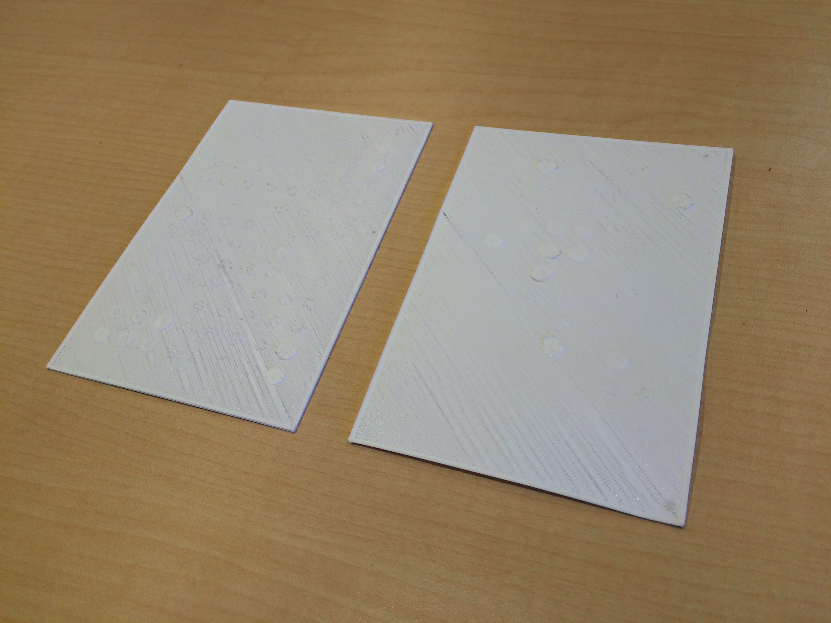
We set one piece in the oven at 60 degrees C to melt, and two others were left at room temperature in the lab. All three pieces warped and shrank, folding the plungers inward. Furthermore, we found the structure to be quite soft when immediately removed from the oven. The warping and shrinking meant that the piece couldn’t properly fit in the well plate with free movement. With Phil Cook’s help, we were able to reduce warping by reheating and cooling, but the shrinking had taken its toll.

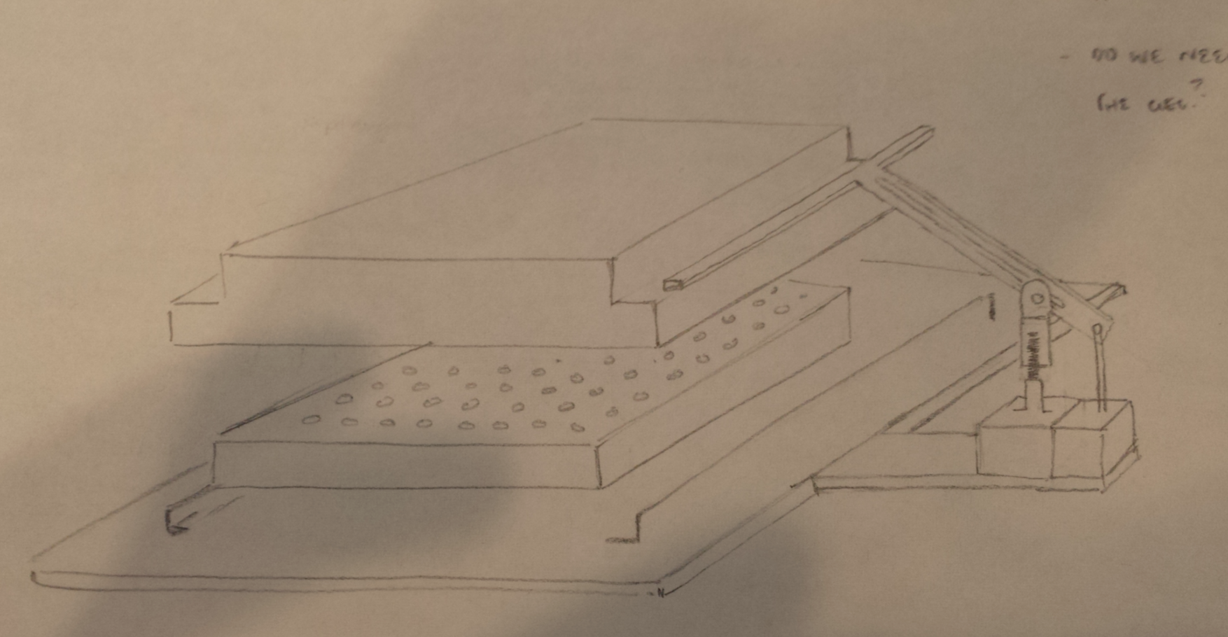
Phone calls with the manufacturer revealed that warping is a common occurrence with designs that have a thin, flat sheet (the base of the plungers). 3D systems recommended 1) thickening the base 2) reprint with the piece slightly rotated about the z-axis, and 3) melt the wax without rapidly heating and cooling the piece.

Thankfully, the final product supported free movement through the wells and was sufficient for a proof of concept. It should be noted, however, that the piece still warped and shrank, even with a 5mm base.

Given our experiences with 3D printing and conversations with manufacturing, it seems that this particular design is not right for printing. The materials cannot support the thin base and repetitive column design. Instead, we propose looking into laser cutting or suction molding.

Coding

Programming the Arduino microprocessor to control the linear motors was based on (1) the parameters for cycling the actuators (and thus plunger array) up and down, and (2) the capabilities and limits of both the microcontroller and microprocessor.  Specifically, the actuators needed to cycle between 2 positions — the start and final position, or the “compression off” and the “compression on” positions, which were separated by just a few millimeters.  The linear motors each had an on-board feedback systems able to to detect position.  Whereas the microcontroller cannot detect position, it can detect and control the length of time that current is being applied to the motors to cause actuation at a constant rate.  Thus, multiplying the the rate constant by time, the microprocessor is able to detect position.

To control the location, and command the cyclical actuation, a for-loop was implemented. The for-loop is a conditional command that dictates “if condition X is met, then proceed to the next step, and if condition X is not met, repeat a function Y.”  Thus, in such a system, function Y will be repeated until condition X is met.  In this case, the for-loop controlled for position, and increased (or decreased) the length of the motor incrementally.  If the position of the actuator arm was at position 0, and the ultimate goal was to get to position a position, “10” the actuators were commanded to actuate to position 1. This would then be compared to the desired position (10).  Since position 1 is less then position 10, the actuators would then be commande to actuate another 1 unit, and so on, until position 10 was achieved.  At this point, the system would reverse until position zero was achieved. This cycle would repeat 100 times, at which point the actuators would go to “neutral position,” in which they were raised to their maximum length, to allow for access by a fluid handling arm or other implementation.

Screen Shot 2014-12-17 at 5.52.32 AM

Milling and Fabrication

Whereas the plunger array was fabricated by 3D printing, machining and milling was selected as the method for fabricating the arms, base, and stage of the system.

All parts were milled from PVC.  A large block of PVC was ordered, and rough estimates of each piece’s dimension were cut with a band saw.

Subsequently, a milling machine (shown below!) was used to to attain exact dimensions, accurate to within a few thousandths of an inch, and with angles accurate within a few thousandths of a degree.

Screen Shot 2014-12-17 at 5.50.07 AM

Each piece — the base, the stage, and both arms were cut and milled.  The component of the arms that make contact with the plunger plate were rounded out to add tolerance; even if the actuation timing was slightly imperfect amongst the 2 actuators, both would be able to contact the plunger array and actuate directly downward.

The arms were placed perpendicular to — and at the edge of both lengthwise sides of — the base. Holes were drilled and threaded for screws. Screws were placed into secure the arms to the base.  The stage was secured to the base in a similar fashion, with bolts to enable the motion of the arms when actuated by the linear motors.  Holes were drilled to place screws to mount the linear motors.  The linear motors were secured to the base, and bolted to the arms to enable their controlling of the arms.  The motors were integrated with the microcontroller and the fabricated system was tested.

Here’s Benji hard at work!

Screen Shot 2014-12-17 at 5.50.18 AM

The Legendary Battle of the Bots

The results of the Drawbot Competition are in! Drumroll please….

10 points to Gryffindor (whoops, I mean Ted and Benji) for winning the competition!

The video of their Drawbot is posted below for your merriment:

Here’s the video of AK and Weiqing’s Drawbot:

And finally, Olivia and Kieran’s Drawbot:

It’s interesting to note that although several of the team members worked together to try and learn Arduino as well as figure out the geometry of the stepper motor/Drawbot specifics, each of the three teams ended up with a different strategy when it came down to coding.

Lessons from the Lulzbot Bullpen, Part One

In order to 3D print our parts, Kevin has graciously allowed us to use the Lulzbot TAZ 4 3D Printer that’s in his lab. Just as a quick overview of what we’re up against: the Lulzbot TAZ offers important upgrades to traditional 3D printing that make it even more robust and capable than before, especially in the context of print quality and consistency. It’s also able to print using a variety of traditional filaments such as PLA, ABS, and HIPS as well as non-traditional filaments derived from nylon, wood, stone, and rubber precursors. Fun fact for your next trivia night: the Lulzbot 3D printers are the first hardware products to receive the Respect Your Freedom certification from the Free Software Foundation, meaning users can not only modify and adapt the various pieces of the Lulzbot to fit their needs but also use free software programs such as FreeCAD, OpenSCAD, and Slic3r to feed their CAD files into the printer.

Here’s a video from the company if you got bored of reading the above and are just about ready to move on to the next paragraph in this blog post:

Stock photos and videos aside, here’s an actual picture of the Lulzbot in Kevin’s Lab:

IMG_0856

With Pete, Joe, and Mike’s help, we were able to figure out how to convert our SolidWorks files into a format that is recognizable by the Lulzbot.

Slic3r is a tool that allows conversion of our 3D printing model into a format that the printer is able to recognize. It cuts the model into horizontal slices or “layers”, generates appropriate toolpaths to fill these layers, and calculates the amount of material that needs to be extruded to fit the right dimensions.

Here’s a picture of the “layers” that were generated by Slic3r:

Screen Shot 2014-11-21 at 2.14.41 PM

Once this was done, the next step was to print! Here’s a picture of the Lulzbot lulzbot-ing:

IMG_0859


All’s well on the field, right?

Wrong.

After the first (second, third, who’s counting really?) few times we tried printing, the printer stopped printing as soon as the base layer was extruded and set. In other words, the 96 plungers that are the most crucial aspect of this plunger piece were MIA. And we ended up with only the flat base (shown below), appropriately titled, “The Postcard.”

IMG_1466


Moving on to the Major Leagues (i.e. 3D Printing)

After Kieran Michelangelo-ed our somewhat vague sketches into this beautiful piece of artwork (I hear the Louvre is currently trying to outbid the MET):

Screen Shot 2014-11-21 at 1.46.38 PM

the next step was to try and replicate some of these parts in SolidWorks- starting with the Plunger piece that will serve to provide compression to each of the gels in 96 wells. After some necessary head-banging and a few cups of coffee, we were finally able to finish the design of our initial plunger piece.

Screen Shot 2014-11-21 at 1.53.16 PM

Will it work? Will it not work? Are we going to be heading to the World Series? Stay tuned…

SolidWorks Tutorial

In order to help us take our sketches from 2D to 3D, we had Pete from Kevin’s lab help us learn how to CAD in SolidWorks. Pete first started by demonstrating some of the various SolidWorks features that would be relevant to our device and project. These included features such as the boss extrude, cut extrude, linear sketch pattern, rotating about an origin, etc. Here’s a picture of Pete in action:

IMG_1359

Then, we split up into two groups with the six of us in one group and Pete in a group by himself (if that gives you any indication of our expertise matched up with Pete’s) and simultaneously tried to replicate the design of a 24-well plate.

Here’s a picture of Olivia and Ted working diligently to CAD a super-human 24-well plate (jk, y’all):

IMG_1360