UPDATE: 3D Printing the Plungers

RECAP:

We chose to use 3D printing to manufacture the LidPlungers because the piece required precise and accurate dimensions to achieve uniform compression.

Our first attempts at printing used the Lulzbot TAZ4 with Kira (software) rendering software. The Lulzbot is a higher-end consumer 3D printer with ~75 micron resolution and can support multiple materials for printing.


UPDATE:

Our specific design turned out to be extremely challenging for the Lulzbot. On our first print attempts, the printer would lay the base structure before plastic built up at the release valve, causing the printer to fail. Conversations with the manufacturer revealed that the Lulzbot might not be able to handle repetitive, small designs (like the plungers) because it requires the plastic flow to start and stop so rapidly.

While a switch from Kira to Slice3 rendering software was able to get the printer to complete the piece, the final product was not structurally sound. Fragments of plastic were breaking off and the piece was extremely flexible.

The team switched to printing on the 3D Systems Projet 3500 HD max, recently set up in the Mount Sinai Prototyping Center. A few features made this the more attractive printer; 1) it could print with much higher resolution, 2) its proprietary plastic would harden after printing, reducing breaking and bending, 3) it simultaneously printed a supporting wax to ensure no structural deformation.

The final product seemed extremely promising. The structure seemed solid and accurate, however, we couldn’t confirm until the wax melted away.

We set one piece in the oven at 60 degrees C to melt, and two others were left at room temperature in the lab. All three pieces warped and shrank, folding the plungers inward. Furthermore, we found the structure to be quite soft when immediately removed from the oven. The warping and shrinking meant that the piece couldn’t properly fit in the well plate with free movement. With Phil Cook’s help, we were able to reduce warping by reheating and cooling, but the shrinking had taken its toll.

Phone calls with the manufacturer revealed that warping is a common occurrence with designs that have a thin, flat sheet (the base of the plungers). 3D systems recommended 1) thickening the base 2) reprint with the piece slightly rotated about the z-axis, and 3) melt the wax without rapidly heating and cooling the piece.

Thankfully, the final product supported free movement through the wells and was sufficient for a proof of concept. It should be noted, however, that the piece still warped and shrank, even with a 5mm base.

Given our experiences with 3D printing and conversations with manufacturing, it seems that this particular design is not right for printing. The materials cannot support the thin base and repetitive column design. Instead, we propose looking into laser cutting or suction molding.

Coding

Programming the Arduino microprocessor to control the linear motors was based on (1) the parameters for cycling the actuators (and thus plunger array) up and down, and (2) the capabilities and limits of both the microcontroller and microprocessor.  Specifically, the actuators needed to cycle between 2 positions — the start and final position, or the “compression off” and the “compression on” positions, which were separated by just a few millimeters.  The linear motors each had an on-board feedback systems able to to detect position.  Whereas the microcontroller cannot detect position, it can detect and control the length of time that current is being applied to the motors to cause actuation at a constant rate.  Thus, multiplying the the rate constant by time, the microprocessor is able to detect position.

To control the location, and command the cyclical actuation, a for-loop was implemented. The for-loop is a conditional command that dictates “if condition X is met, then proceed to the next step, and if condition X is not met, repeat a function Y.”  Thus, in such a system, function Y will be repeated until condition X is met.  In this case, the for-loop controlled for position, and increased (or decreased) the length of the motor incrementally.  If the position of the actuator arm was at position 0, and the ultimate goal was to get to position a position, “10” the actuators were commanded to actuate to position 1. This would then be compared to the desired position (10).  Since position 1 is less then position 10, the actuators would then be commande to actuate another 1 unit, and so on, until position 10 was achieved.  At this point, the system would reverse until position zero was achieved. This cycle would repeat 100 times, at which point the actuators would go to “neutral position,” in which they were raised to their maximum length, to allow for access by a fluid handling arm or other implementation.

Screen Shot 2014-12-17 at 5.52.32 AM

Milling and Fabrication

Whereas the plunger array was fabricated by 3D printing, machining and milling was selected as the method for fabricating the arms, base, and stage of the system.

All parts were milled from PVC.  A large block of PVC was ordered, and rough estimates of each piece’s dimension were cut with a band saw.

Subsequently, a milling machine (shown below!) was used to to attain exact dimensions, accurate to within a few thousandths of an inch, and with angles accurate within a few thousandths of a degree.

Screen Shot 2014-12-17 at 5.50.07 AM

Each piece — the base, the stage, and both arms were cut and milled.  The component of the arms that make contact with the plunger plate were rounded out to add tolerance; even if the actuation timing was slightly imperfect amongst the 2 actuators, both would be able to contact the plunger array and actuate directly downward.

The arms were placed perpendicular to — and at the edge of both lengthwise sides of — the base. Holes were drilled and threaded for screws. Screws were placed into secure the arms to the base.  The stage was secured to the base in a similar fashion, with bolts to enable the motion of the arms when actuated by the linear motors.  Holes were drilled to place screws to mount the linear motors.  The linear motors were secured to the base, and bolted to the arms to enable their controlling of the arms.  The motors were integrated with the microcontroller and the fabricated system was tested.

Here’s Benji hard at work!

Screen Shot 2014-12-17 at 5.50.18 AM

Make gel discs and perform Alamarblue assay for the experiment

Agarose and Alginate have been commonly used in the literature to make 3-D culture constructs. The advantage of alginate is that it does not need to be heated up to solidify. You just simply add sodium alginate to a calcium solution and you get your gel! So we thought to take advantage of this property of alginate to make gel constructs without killing our cells by heat.

We mixed 2% sodium alginate with 102 mM calcium salt solution in the well, hoping it will form a nice disc. But nope! We got this.

Try to make alginate gel

Try to make alginate gel

An amorphous blob with uneven consistency!! After consulting with a gel expert in the lab, we were told that in order to make an alginate gel with a defined shape, we will need to construct a negative mold made of agarose and pour the alginate solution into the mold. Seal it up and soak the agarose mold with the alginate in it into a pool of calcium solution. The calcium ions will diffuse through the agarose gel and react with the sodium alginate inside. Then we will get nice alginate disc gels.


Considering the complexity of making alginate gels, we decided to use agarose to make our disc constructs. Although we have to heat the agarose solution to a boiling temperature, we can choose to use a low-melting agarose. Like this one!

Low-melting agarose

Low-melting agarose

Its gelling temperature is also pretty low, much lower than 37 degrees celsius. GREAT! So we wouldn’t kills cells by seeding them with hot agarose solution!


Next, we need to figure out how to make round gel discs to be compressed by our bioreactor.

Gel sandwich construct

Gel sandwich construct


We initially designed the the gel constructs to be consisting of two layers agarose gels with a thin layer of cells in the middle. Ideally this could facilitate the confocal imaging process as all cells can be captured in one layer and cells are more accessible to the surrounding media. However, our approach to make the sandwich construct failed on multiple levels!


First, we encountered problem of making gels using the tools we designed.

The gel poker

The  GelMolder

The gel poker

The GelPoker


We designed the gel molder (3-D printed) that was supposed to cut 96 gel discs and transfer them to the well plate. And then we would use the poker to push out the gel discs through the holes of the molder. This way we could make the gel constructs in a high-throughput fashion.

However, the gel molder we 3-D printed was not picking up the discs from the gel slab. And the length of the plungers of the poker was too short that it could not reach to the  other end of the hollow wells and thus could not touch the 3 mm height gels discs.

As a result, we had to use a biopsy punch to punch the gel slab 96 times and use a tweezer to pick up the discs and transfer them into the well plate! This step really needs to be automated in the future, otherwise it defeats the whole purpose of making a “high-throughput” bioreactor.

IMG_1039

Make a punch

IMG_1041

Pick up the gel disc with a tweezer

IMG_1043

In the process of transferring gel constructs. BE VERY CAREFUL!

IMG_1038

Good luck try putting the gel construct into the center of the wells!


Another problem with making a gel sandwich is the uneven gel surface. We poured a calculated amount of agarose on to a petridish to make the desired height and waited for it to gel before we added a layer of cells. Without any constraints on the top, the top surface can assume any form. It can bulge, distort and disturb. Not cool. It led to the formation of discs of uneven height. Yuk!

What’s more, as we added the second layer of gel and tried to pick out the sandwich construct by the tweezer, the two layers of gels slipped apart!!! NIGHTMARE!!!!

At this point, it is clear that the gel sandwich approach was not the best way to make little gel discs. And we really needed to figure out a way to make flat, nice gel slabs!


As we are smart, smart students, we quickly found another way to make perfectly flat gel slabs!

Make gel slab using Western Blot!

Make gel slab using Western Blot!

As shown in the picture, we used two pieces of glass separated by a spacer (the black rubber piece) of 2.8 mm thickness to make gel slabs. The thickness of the spacer is the desired height of our gel discs. By putting the glasses onto a stand that is usually used to make gels for Western blot, we were able to seal one end of the glass pieces and pour the agarose solution from the top. After removing the glass slides when the gel solidified, we got a super nice gel slab! Tata….

Perfectly flat gel slab!!

Perfectly flat gel slab!!

We first heated up a 4% agarose solution to its boiling temperature. After it’s cooled down below body temperature,we mixed it with an equal volume of tissue culture growth medium (pink) with a certain cell concentration to make an agarose solution with a final concentration of 2%. Then we loaded our agarose solution seeded with cells on to the gel making device and wait for it to solidify.  We measured the actual height of the gel disc to be 2.57 mm, a little less than the spacer due to the force applied by the clamps.

Measuring the actual height of our gel construct!

Measuring the actual height of our gel construct!


Great! Now we have made gel discs seeded with cells. The next thing would be performing an assay for testing cell viability. We want to make sure that 1) the reagent of the assay can diffuse through the gels and get to the cells; 2) the cells are healthy and alive inside the gel constructs. We chose to use alamarBlue assay because it’s simple to perform and it is not an end-point assay. You can keep testing cell viability over time.  It indicates cell health by using the reducing power of living cells to quantitatively measure the proliferation of various kinds of cells. Resazurin, the active reagent of alamarBlue, is a non-toxic, cell permeable compound that is blue in color and virtually non-fluorescent. Upon entering cells, resazurin is reduced to resorufin, a compound that is red in color and highly fluorescent. Viable cells continuously convert resazurin to resorufin, increasing the overall fluorescence and color of the media surrounding cells.

We incubated the cell-seeded gel constructs with alamarBlue in the medium for overnight. The next day, to our delight, the color of the well turned pink from blue!!

AlamarBlue Assay results

AlamarBlue Assay results

The right rectangular comes from the medium incubated with cells in gels. The pink color indicates that the cells are alive and healthy in gels! High five!

Now that we know that alamarBlue assay can be successfully performed in our specific case, we can go ahead to test if the compression will have an effect on cell viability. According to literature, intervertebral cells subject to physiological compression actually become more healthy than the cells not subject to the compression. On the other end, cells subject to excessive compression will have decreased viability than the cells subject to physiological or no compression. It will be interesting to test these established  observations on our bioreactor to validate the device.


The Legendary Battle of the Bots

The results of the Drawbot Competition are in! Drumroll please….

10 points to Gryffindor (whoops, I mean Ted and Benji) for winning the competition!

The video of their Drawbot is posted below for your merriment:

Here’s the video of AK and Weiqing’s Drawbot:

And finally, Olivia and Kieran’s Drawbot:

It’s interesting to note that although several of the team members worked together to try and learn Arduino as well as figure out the geometry of the stepper motor/Drawbot specifics, each of the three teams ended up with a different strategy when it came down to coding.

Lessons from the Lulzbot Bullpen, Part One

In order to 3D print our parts, Kevin has graciously allowed us to use the Lulzbot TAZ 4 3D Printer that’s in his lab. Just as a quick overview of what we’re up against: the Lulzbot TAZ offers important upgrades to traditional 3D printing that make it even more robust and capable than before, especially in the context of print quality and consistency. It’s also able to print using a variety of traditional filaments such as PLA, ABS, and HIPS as well as non-traditional filaments derived from nylon, wood, stone, and rubber precursors. Fun fact for your next trivia night: the Lulzbot 3D printers are the first hardware products to receive the Respect Your Freedom certification from the Free Software Foundation, meaning users can not only modify and adapt the various pieces of the Lulzbot to fit their needs but also use free software programs such as FreeCAD, OpenSCAD, and Slic3r to feed their CAD files into the printer.

Here’s a video from the company if you got bored of reading the above and are just about ready to move on to the next paragraph in this blog post:

Stock photos and videos aside, here’s an actual picture of the Lulzbot in Kevin’s Lab:

IMG_0856

With Pete, Joe, and Mike’s help, we were able to figure out how to convert our SolidWorks files into a format that is recognizable by the Lulzbot.

Slic3r is a tool that allows conversion of our 3D printing model into a format that the printer is able to recognize. It cuts the model into horizontal slices or “layers”, generates appropriate toolpaths to fill these layers, and calculates the amount of material that needs to be extruded to fit the right dimensions.

Here’s a picture of the “layers” that were generated by Slic3r:

Screen Shot 2014-11-21 at 2.14.41 PM

Once this was done, the next step was to print! Here’s a picture of the Lulzbot lulzbot-ing:

IMG_0859


All’s well on the field, right?

Wrong.

After the first (second, third, who’s counting really?) few times we tried printing, the printer stopped printing as soon as the base layer was extruded and set. In other words, the 96 plungers that are the most crucial aspect of this plunger piece were MIA. And we ended up with only the flat base (shown below), appropriately titled, “The Postcard.”

IMG_1466


Moving on to the Major Leagues (i.e. 3D Printing)

After Kieran Michelangelo-ed our somewhat vague sketches into this beautiful piece of artwork (I hear the Louvre is currently trying to outbid the MET):

Screen Shot 2014-11-21 at 1.46.38 PM

the next step was to try and replicate some of these parts in SolidWorks- starting with the Plunger piece that will serve to provide compression to each of the gels in 96 wells. After some necessary head-banging and a few cups of coffee, we were finally able to finish the design of our initial plunger piece.

Screen Shot 2014-11-21 at 1.53.16 PM

Will it work? Will it not work? Are we going to be heading to the World Series? Stay tuned…

SolidWorks Tutorial

In order to help us take our sketches from 2D to 3D, we had Pete from Kevin’s lab help us learn how to CAD in SolidWorks. Pete first started by demonstrating some of the various SolidWorks features that would be relevant to our device and project. These included features such as the boss extrude, cut extrude, linear sketch pattern, rotating about an origin, etc. Here’s a picture of Pete in action:

IMG_1359

Then, we split up into two groups with the six of us in one group and Pete in a group by himself (if that gives you any indication of our expertise matched up with Pete’s) and simultaneously tried to replicate the design of a 24-well plate.

Here’s a picture of Olivia and Ted working diligently to CAD a super-human 24-well plate (jk, y’all):

IMG_1360

Initial Design Decisions and Sketches

In our previous post we decided that we will create a bioreactor that is able to compress 3D tissue cultures and integrate into a high throughput workflow, and discussed the novelty and potential applications of such a device.

Here, we discuss some initial ideas and some early phase decisions that came up in our design process.

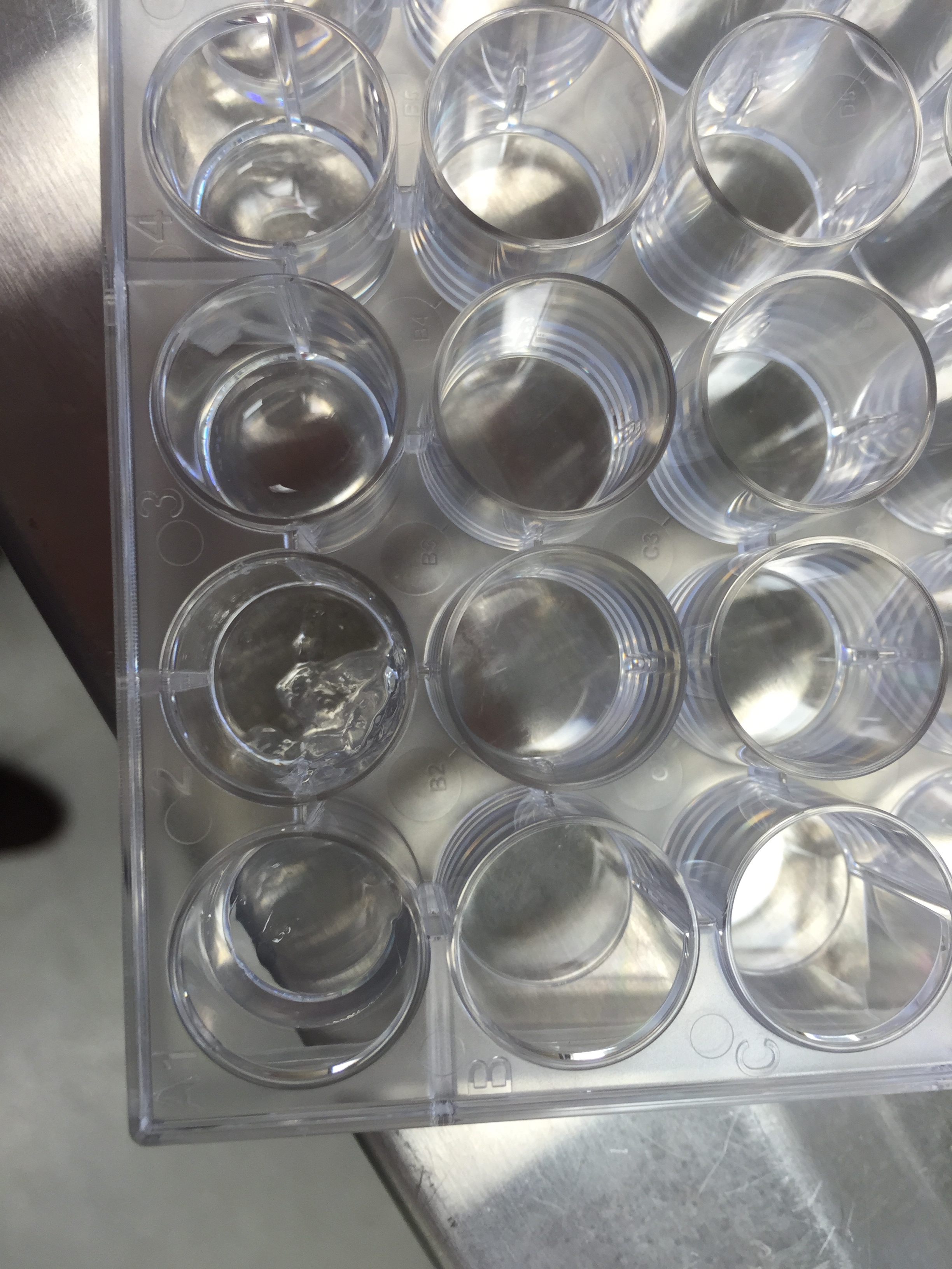
Microtiter plates, sometimes called microwell plates, have become a standard tool for analytical research in the life sciences. They consist of a flat plastic plate with wells arranged in a 2:3 ratio, and standard plate formats include 6-, 24-, 96-, and 384- well matrices. Sigma-Aldrich, a popular lab equipment retailer, has hundreds of products from dozens of brands available online in this format. Most tools for high-throughput life sciences workflows interoperate with this format, so it seemed like a natural choice to center our bioreactor around a microtiter plate.

ISMMS Screening Core

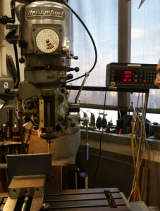
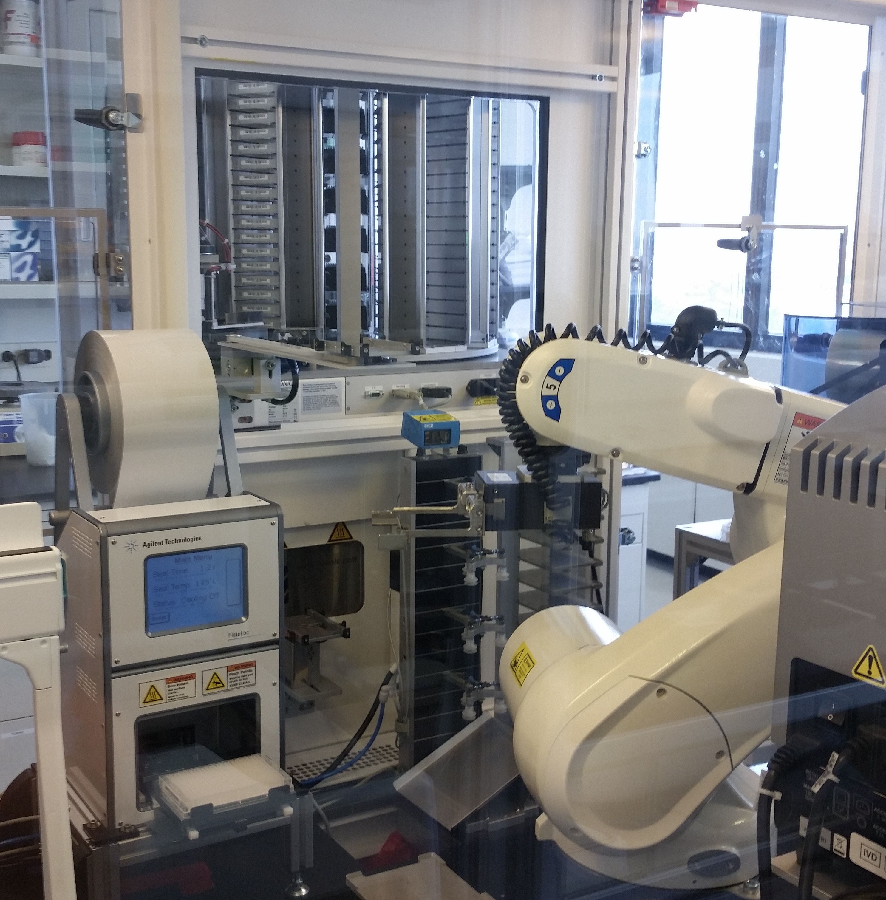
Lab equipment from the ISMMS Integrated Screening Core. At bottom left is a plate sealer with a microtiter plate in its tray. Also pictured are a plate storage unit at top, and a plate handling robot at center.

An early decision was which well format we would target. The tradeoff is between the complexity of the bioreactor in handling more wells at once, and the overall throughput of one device. There was some discussion about what constitutes “high throughput” in the cartilage and tissue engineering field, with some students arguing that dozens of samples would be a significant improvement over current published methods for a compression bioreactor, while others insisted that we could shoot for thousands of samples and only at this scale would we achieve something “high-throughput”.

To minimize the complexity incurred by this tradeoff, we decided that we should try to delegate as many tasks as possible to existing devices in the high throughput workflow. There are already complicated but well-supported solutions for moving plate-size objects around and dispensing liquids into them. It would be costly and redundant for us to implement such functions in our own bioreactor compared with our design facilitating other devices coming in to do the same work.

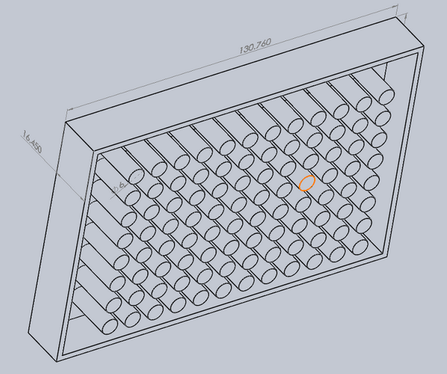
We would then, however, need to design our bioreactor around the requirements of those devices. Regardless of the choice of well format, it was pretty clear our bioreactor would need a “nest”, which is where the microtiter plate would sit. Several nests and a Tecan plate manipulator are shown below.

20141010_104343_Android

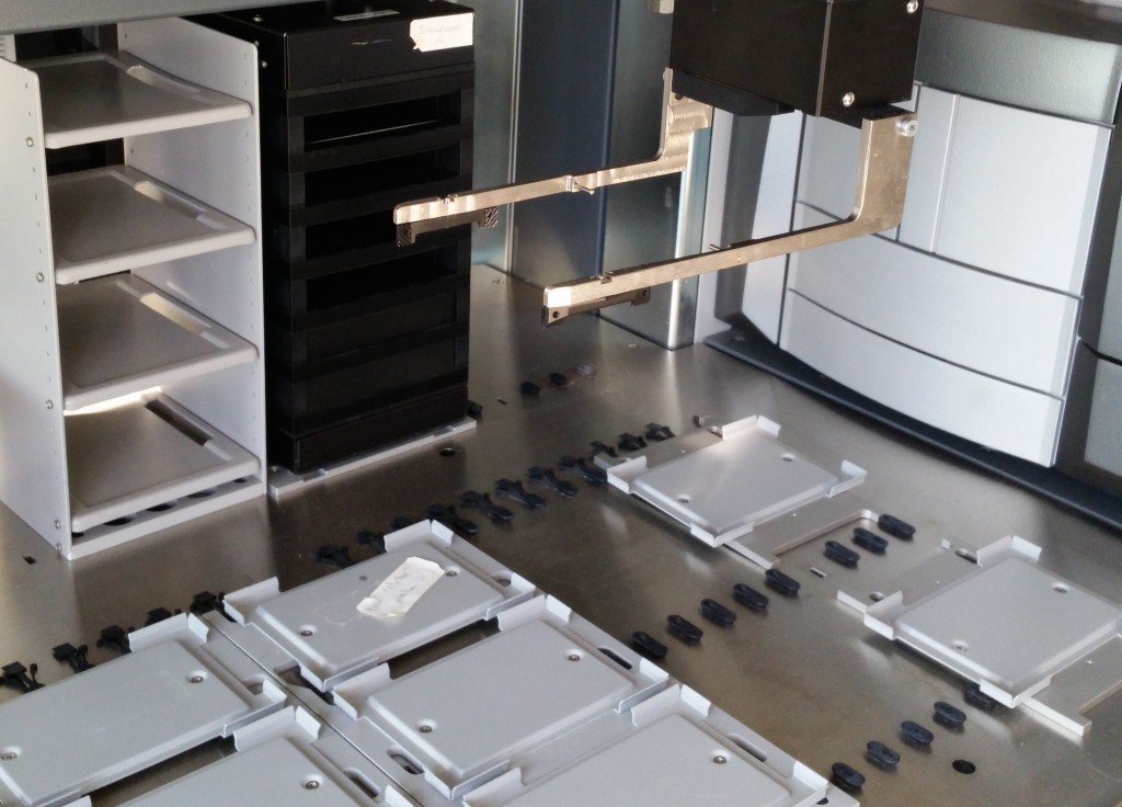
Different plate handling robots have different capabilities for manipulating the plates; for example, both of the previously shown robots can insert a plate into a shelf since they hold the plate from the side. Other robots grip the plate from above, however, and with this configuration our device must expose the entire top surface of the plate in order for it to be removed.

20141010_112701_Android

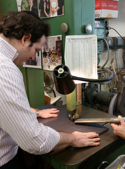
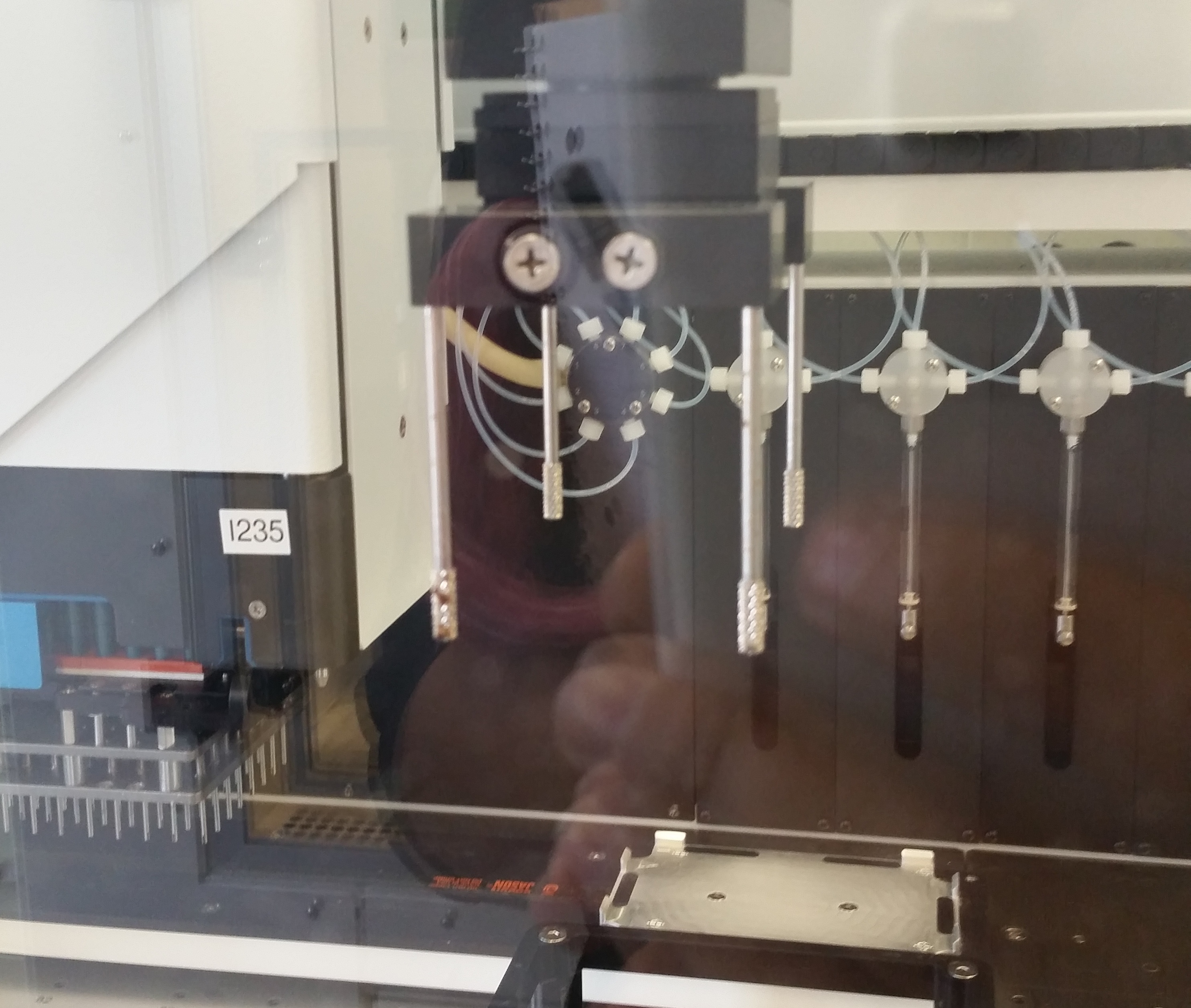
This plate handler grips the plate from the top, using the four grippy rods, and therefore cannot insert the plate into a shelf-like space—it can only drop it into an exposed nest.

We were informed that the latter restriction is pretty common, and the Tecan equipment we would have access to would likely have this same restriction, so we decided to assume a top-gripping plate handler going forward. We would want a robot to be able to manipulate the plate into and out of our device, so that regardless of the well format, a plate handler could swap in dozens of plates for compression in sequence. This is what allows us to jump from, e.g., 96 samples to thousands of samples, if a robot can automate the application of our bioreactor’s compression function to many 96-well plates over the course of one experiment.

Assuming a top-gripping robot and that our compression action would also be applied from the top of a standard microtiter plate required us to consider how our device could alternately attach to the wells from above and subsequently allow them to be exposed for manipulation and liquid exchange. There are a few approaches used by existing devices, such as a “sliding drawer” approach and the “panini press” approach pictured below.

Two approaches to exposing microwell plates; left: "drawer" approach used by a plate reader, right: "panini press" approach used by a thermocycler

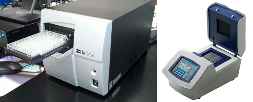
Two approaches to exposing microwell plates for manipulation; left: “sliding drawer” approach as used by a plate reader, right: “panini press” approach as used by a thermocycler

Both of these approaches require a large moving part: either a drawer or a hinge, which would have to be actuated separately from the compression action applied to the wells. In the case of the hinge, a lot of the device would have to live inside a heavy “lid” that might require a significant amount of force to lift off or lock down onto the the plate.

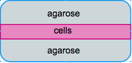
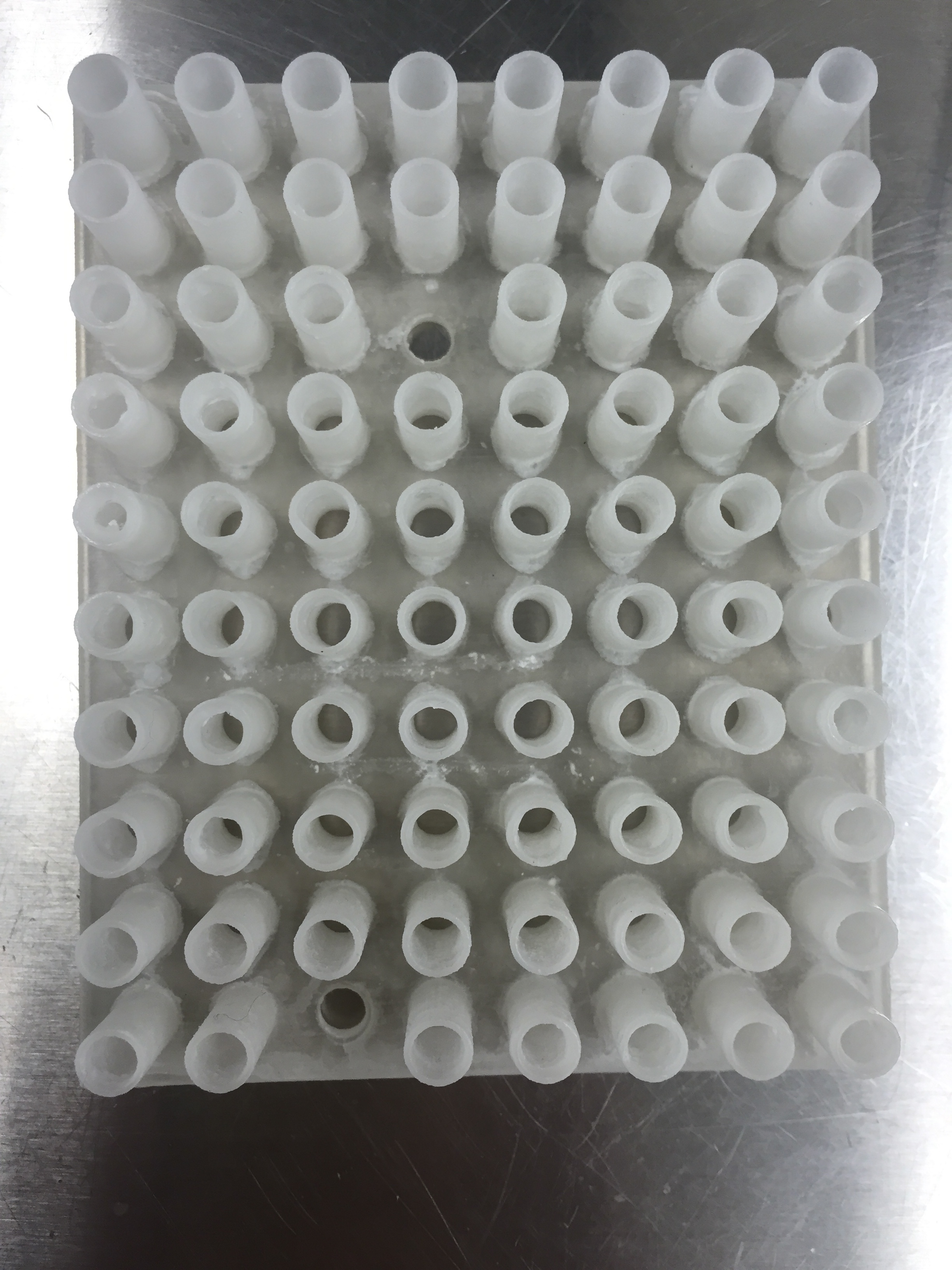
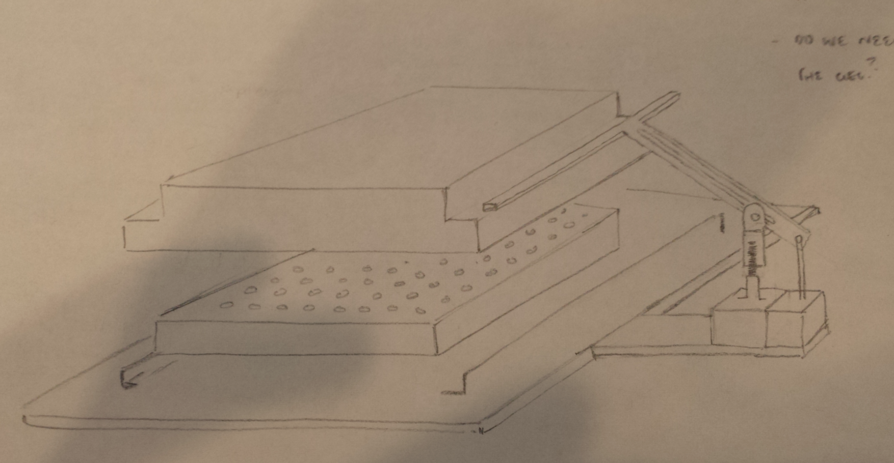
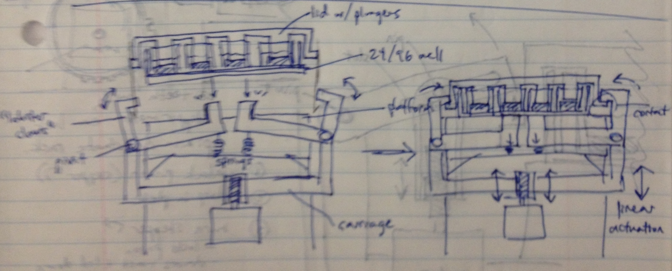
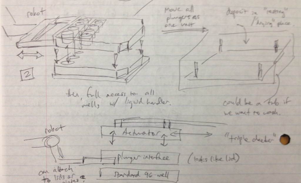
It occurred to us at this point that in order to maintain sterility between samples in wells from different plates, there would need to be an “adapter lid” that can apply the compression to the tissue sample while avoiding direct contact between the culture and the actuation mechanism. This way, one actuation mechanism can operate on multiple adapter lid + microtiter plate pairings, manipulated by the robot, to enable the thousand-sample scale described previously. If the adapter lid is a plastic part, it could be cheaply printed for many plates and autoclaved between runs, and if it were roughly the size of a microtiter plate itself, the plate manipulator robot could lift the adapter lid off of the plate and place it separately onto another nest to allow access to the plate’s wells by a liquid handler. These ideas are expressed in the following design sketches.

image (1)

Dan Felsenfeld of the ISMMS Integrated Screening Core raised the point that if our device lived mostly underneath the plate, like a microplate shaker, it could latch onto it and actuate the plungers from below. This saves horizontal space, which is at a premium inside a liquid handler, and could allow for actuation and latching to be driven by one motor. This idea is incorporated into the following sketch.

claws design

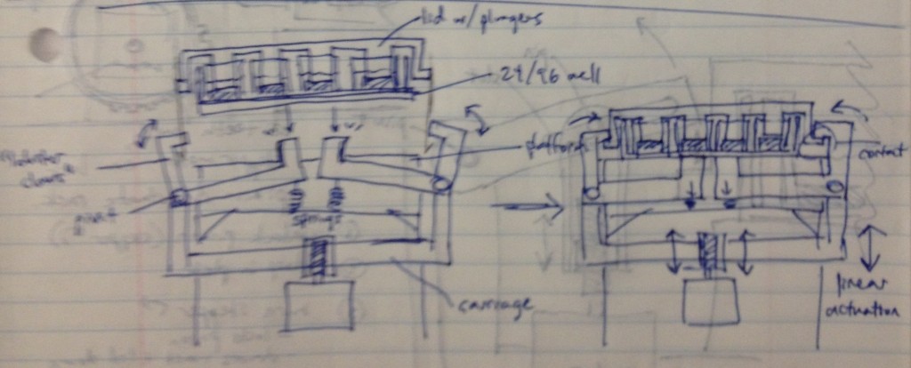
In this design, dropping the plate onto the device causes the rotating claws to latch onto the lid from the sides. The claws can then be actuated by a stepper motor and screw drive from below.

We recognized that this particular design, while attractively compact and utilizing only one motor for actuation, requires a fair number of moving parts. Some of these moving parts may have tight tolerances, particularly the arms that must latch neatly over the edge of the lids while releasing the plate promptly when it is lifted. We considered whether we could move more of the mechanism off to the sides and reduce the number of tricky parts.

image (2)

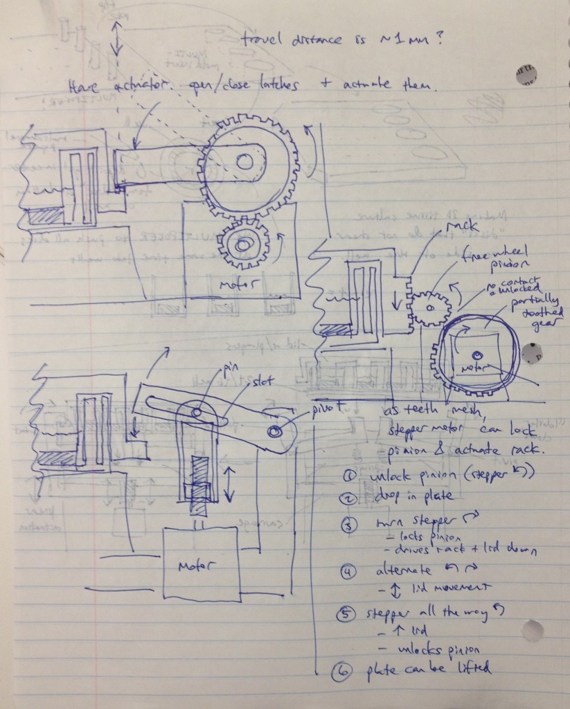
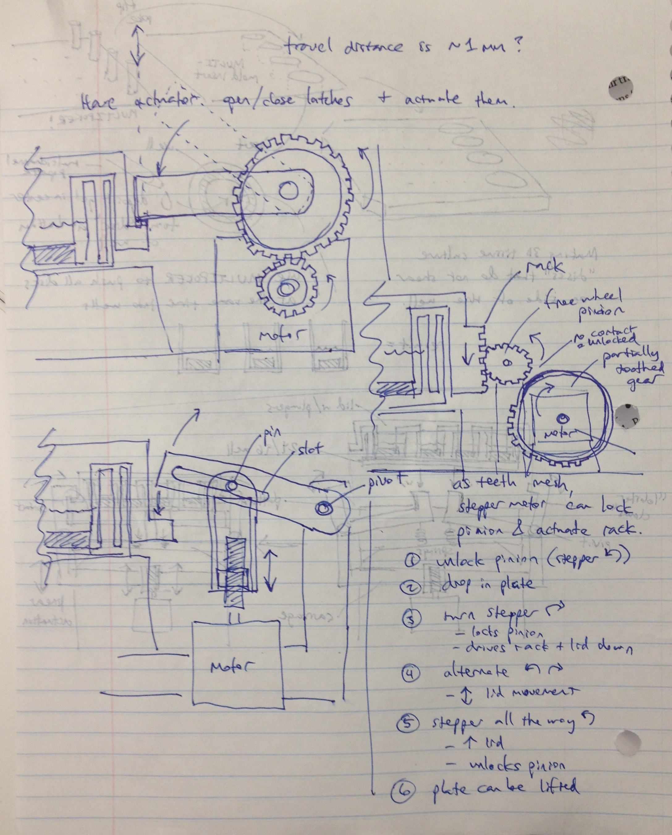
Three possible simpler designs are shown in the sketch above. The rightmost sketch involves a rack that would be printed on the edge of the adapter lid, which engages a freewheel pinion as the plate is dropped onto the bioreactor’s nest. A partially toothed gear could then be rotated by a stepper motor to lock the lid via the freewheel pinion, and then depress it, applying force to the tissue samples.

The other two designs to the left top and left bottom are most analogous to a traffic gate:

url

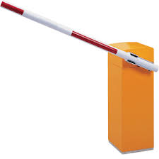
and involve the use of a stepper motor or linear actuator to move an arm up and down that depresses the adapter lid. By rotating the arm sufficiently upward, it can be moved out of the way of any plate manipulators that require access from above.

To keep the motion of these designs symmetrical, the mechanism could be duplicated onto the other side of the device and the arms and motors would be moved in unison via software control.

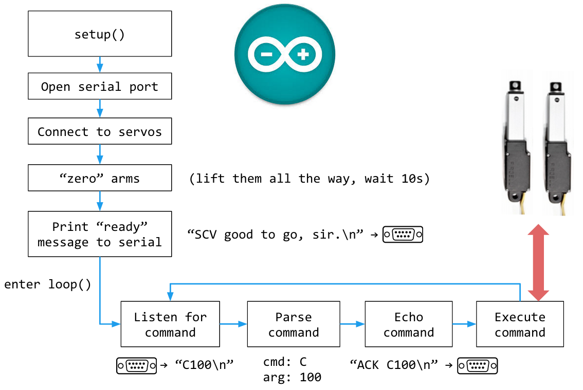
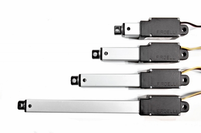
The bottom-left design was considered most attractive overall due to its simplicity and the possibility of altering the compression force by changing the thread count of the screw. Cheap linear actuators based off an internal screw drive are readily available from Firgelli and they are also apparently controllable by Arduino boards.

ID1IMAGE1392329569

Stay tuned for a post detailing how we chose our plate format (24-well vs. 96-well?) and the loading functionality of the bioreactor (hydrostatic pressure vs unconfined compression?) along with other important design decisions.