Complete! Presentation Preparation!

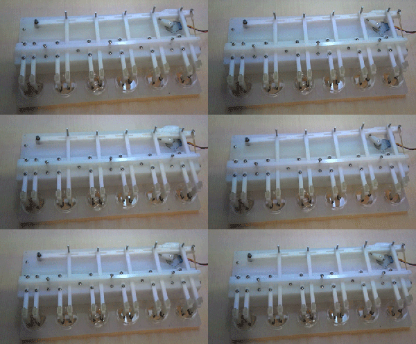
After much hard work the group was able to assemble the Shear Bioreactor Prototype! Right in time for our final presentation tomorrow.

IMG_1957.MOV

The working prototype mechanism of action:

Final product!

(Please click on the picture if the gif does not load)

_______________________________________________________________
I hope you enjoyed the journey as much as we did!

-2013 DTE Team:
Grace, Mitch, Kevin, & Ben

Machining/Assembly Process

The order was successfully given to Arthur and put into the Zahn Center for paddle/tissue fork 3D printing. Our initial meeting them was extremely helpful and we learned to include more tolerance to allow the tissue forks to move in and out of the holder.

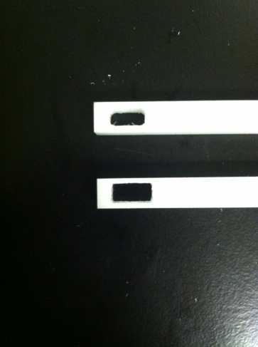
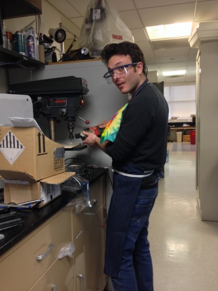
We also began the machining process after receiving the cut pieces from Phillip and his lab.

IMG_1860

IMG_1911

IMG_1859

Machining Planning

We have received all of the materials that we ordered from Adafruit (Arduino accessories) and McMaster Carr. There was some confusion (as there sometimes in with many parts and multiple vendor orders) and some parts were missing/incorrect sizes. After some exchanging and re-ordering, all of the correct parts arrived.

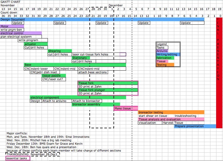
We then composed a Gnantt chart to document what tasks we have left and what pieces needed to be assembled/machined. We considered the available resources and made decisions of what machining we could manage ourselves (with help from Pete, of course), what parts Phillip Cook could make, and what we would have to outsource to the Zahn center.

Screen Shot 2013-12-18 at 6.01.54 PM

We decided that Phillip Cook and Brian would do the initial base cuts (we ordered double the size of the bases needed so we would have a spare) of the two large base pieces and the actuator arms. The Zahn center would 3D print the paddles and tissue forks. Pete and the gang would make drill holes, dish placers, motor slot, etc., and take care of the assembly.

Motor Arduino Programming Beta Version Complete!

Grace, Pete, and Ben have been trying to debug the output speed issues with the current Arduino motor configuration. This project utilizes Arduino Uno with a motor shield as well two 512 step bipolar motors (5V and 12V) as well as a 200 step (12V) and an external power source. The 200 step motor is slightly larger than the other two and has higher torque. This motor was purchased after the fact as the group wasn’t sure if the former motors would have enough power to correctly move the mechanism.

IMG_0726

Issues came about because the motor would output weak force that could be manually stopped fairly easily. Also it took around 3.5 seconds to perform one full rotation. The motors also only rotated in one direction when we expected them to be able turn back and forth.

Through some debugging, the group realized that there was a wiring issue which resolved the rotation issues as well increased the power output. Professor Costa also indicated that a stronger external power source (which the group purchased) would increase the output.

Mitchell, Kevin, and Pete calculated the exact angles the motor has to turn to (45 degrees). Accordingly, the motor will turn 64 steps (512 step motor) in each direction to achieve this.

As of now, the program is complete and will perform said actions upon a user initiated keystroke.

Sketch Optimization and Problem Solving

Kevin continued to work to optimize the SolidWorks file. This was an important step because many of these parts will be sent off for machining and processing (both at Mount Sinai and the Zahn Center at City College). Issues have arisen in terms of connecting the parts of the bases together as well as motor space requirements. There are some problems with motor power and the group ordered a stronger Bipolar Stepper Motor as a possible fall back, but the size of this new motor is a lot larger than the previous one.

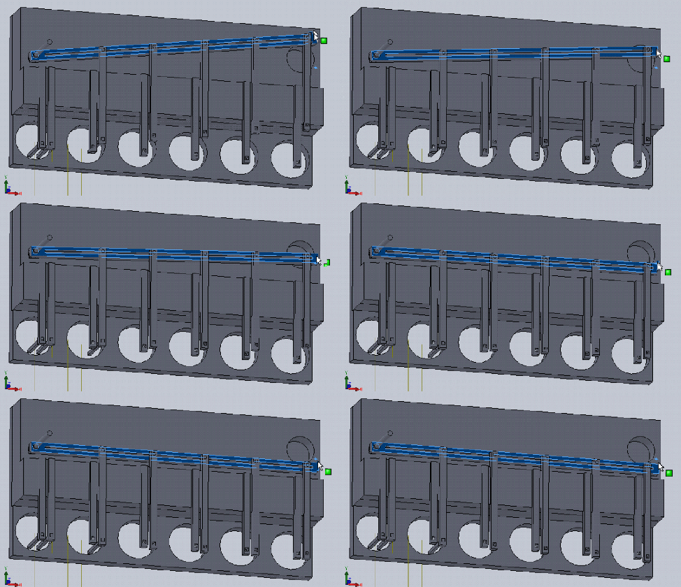
These seemingly minute issues can have large impact on the machining process so these changes are important to finalize early on as to prevent wasting of time/effort/money. Attached is an updated sketch from SolidWorks made by Kevin that demonstrates the bioreactor mechanism of action through a different angle:

Image

Remaining Problems

Today’s lab was spent on working on specific issues we’ve been having:

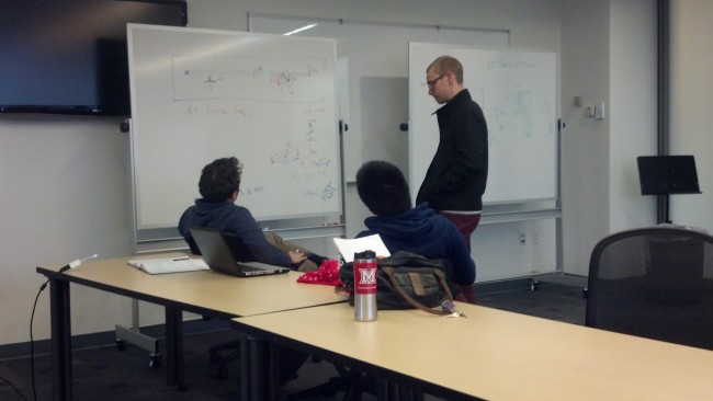
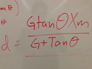
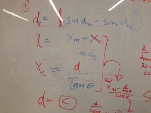
Mitch, Pete, and Kevin are working on the mathematics involved for the specific measurements for the actuator arm’s placement on the base.

Image

IMG_1875 IMG_1874

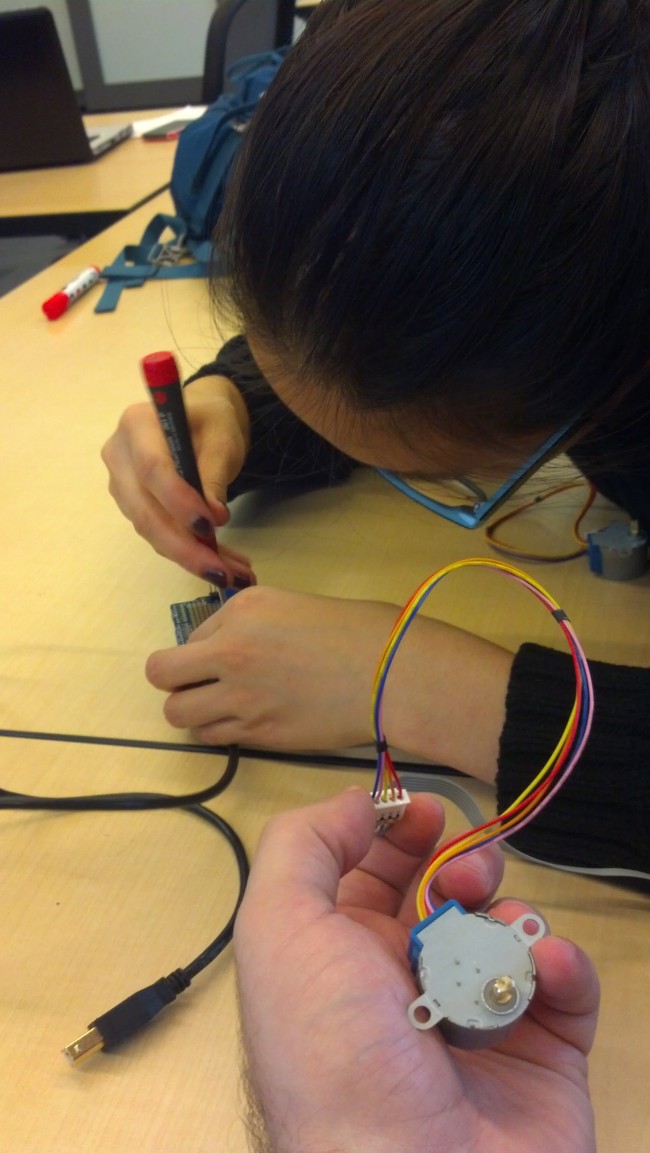
Grace and Ben are working on configuring the Stepper motor with Arudino

Image

3D Printing of Small Parts Process

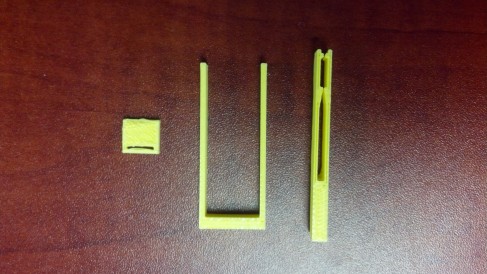
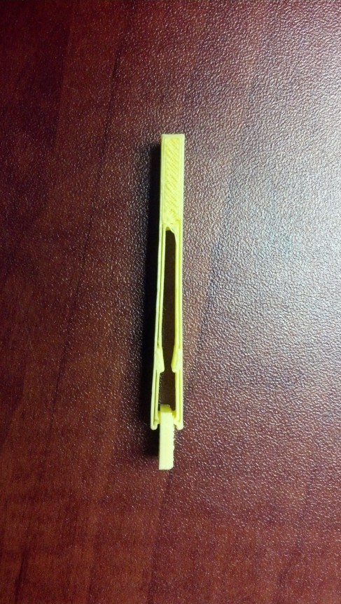
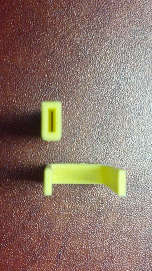
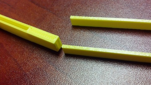
Grace has been in contact with Arthur from the Zahn Center at City College who will be helping us 3D print some of the small pieces that connect to the tissue and dish forks. We had our first iteration of parts printed as a test from MakerBot.

ImageImageImageImage

It is clear that we did not put enough of a tolerance between the parts as they weren’t able to connect properly. The flimsy material of the MakerBot might not be sufficient for our purposes. We are currently working on a updated iteration.

Machining Process

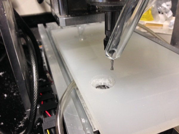
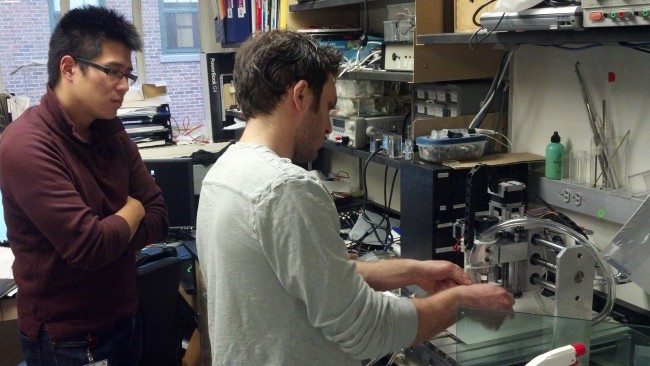
With the SolidWorks file almost finalized, Pete helped us import the sketch file to CNC machine for initial machining of the base components. We realized that we did not add holes for the base pieces, which had to be updated.Image

Image

Testing limits of sample tissue properties

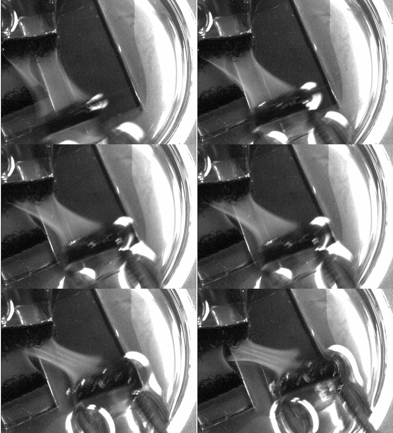
With our test velcro-tissue samples solidified. Dr. Costa suggested the lab do a simple shear stress test on the samples. For each sample, we manually sheared the tissue with tweezers in a vertical direction to gain a sense of the tissue endurance. What follows is an example:


Tissue Movement